The Arduino ESR project is moving along, albeit a little slowly. The miniature OLED displays finally showed up, and I have to admit, I really like them. A lot. I’ve come up with a concept that will use the small OLED as a dynamic menu, with corresponding pushbuttons to move and select options.
The primary interface module is done. As you can see from the photo below, it has the LCD display, the OLED display, four 6mm x 6mm pushbutton switches (with caps installed), and four LEDs.
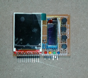
The protective plastic is still on both of the displays (and I would recommend leaving it on until everything is done). And, yes, it’s not the neatest looking thing, but the perfboard was what I had on hand and it was the right size. Here’s a look at the back side of the module:

I hate working with this type of perfboard, for a couple of reasons: First off, it’s single-sided, so there is no plate-through on the holes and the solder tends to clump up on the pad; Secondly, the pads are too close to each other, so solder bridges are a problem. I use a liquid flux to help with the soldering, and I just ordered a tinning solution mix (makes about 2 pints, if I make it all at once). I’ve ordered some double-sided perfboards, like the one shown below, with small pad donuts, so I’ll see how well those work out.

One problem with perfboards (besides the other issues I have with them) is how to connect to them. I solved this with the ESR interface module by using pin headers. A right-angle pin header doesn’t take up a lot of vertical space and they can be soldered anywhere on the back of the PCB. I fashioned the right-angle pin headers shown in the photo the hard way from standard headers, because I’m out of right-angle parts and the replacements haven’t shown up yet (I also tend to be impatient, but that’s a different issue). I bent the short pins using a pair of needlenose pliers and a small vise. Not elegant, perhaps, but it worked.
Components near the edges of the PCB can be connectorized with a standard straight pin header, as shown in the photo above. Assuming that the short pins on the header are long enough to reach the pads with the component leads, then it’s just a matter of lining up the header and soldering it. As you can see, I’ve brought out the LEDs and the connections for the LCD display using this technique.
While this does work, it’s not ideal. The connection between the component pins and the header pins is entirely dependent on the solder between them. There is no mechanical support to speak of, just the solder. A better approach would be to solder the headers into the PCB and connect each pin to the component PCB using a trace. For the final version of the prototype the interface module will be a custom PCB, and that will deal with a lot of these issues.
The LCD module from Keyes turned out to be more of a challenge than I had anticipated. Someone apparently thought it was a good idea to install a right-angle header with the pins coming out to the front side of the module. Where the screen is. Really? There is no way to flush-mount this module as built. So I replaced the original header with a straight header coming out the back. I’ve ordered some replacements with pins in the correct orientation, so I may end up replacing the Keyes unit with something else if I can’t get it to behave. But right now it’s working, and that’s what I was after.
Next time I’ll have a GIF showing both displays running at the same, along with the prototype menu selection function.


0 Responses to “The ESR electronics Tricorder: Update”